| General information | |
| Access mode |
- |
| Infrastructure name and acronym | Highly Instrumented Reactor for Atmospheric Chemistry (HIRAC) |
| Photos |
 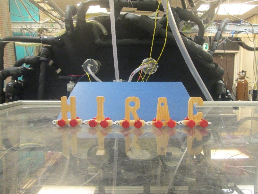 |
| Location | School of Chemistry, University of Leeds, Leeds, LS2 9JT, United Kingdom 53.8067° N, 1.5550° W |
| Website | https://hirac.leeds.ac.uk |
| Legal name of organisation operating the infrastructure | University of Leeds |
| Description of the infrastructure | |
| Brief general description of the infrastructure to which access is offered |
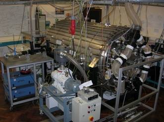
HIRAC is a stainless steel, 2 m3 cylindrical simulation chamber equipped with a variety of instrumentation to monitor both radicals and stable species. The focus of HIRAC is on gas phase chemistry. |
| Services currently offered by the infrastructure and its research environment |
N/A |
| Modalities of access and support offered under EUROCHAMP-2020 | |
| Typical duration of work |
N/A |
| Community/user type served |
N/A |
| Scientific and technical support offered | N/A |
| Logistic and administrative support offered | N/A |
| Person in charge of the infrastructure |
Prof. Paul Seakins, School of Chemistry, University of Leeds, p.w.seakins@leeds.ac.uk |
| Extended technical information | |
| Physical description | The HIRAC chamber is a 2 m3 cylindrical simulation chamber constructed from grade 304 stainless steel which allows operation over a range of temperatures and pressures with several flanges to allow access for instrumentation and sampling. Dimensions: Length: 2 m Width: 1.2 m Volume: 2.25 m3 Internal surface area: ~10 m2 S/V ratio: 5.8 m-1 RH range: 0-50% (generally run under dry conditions, but humidity can be adjusted) Temperature range: 250 – 350 K Pressure range: 50 – 1000 mbar (potential to operate at higher pressures, but would require certification) Access: 2 x ISO-K500 access flanges on the end walls. 2 x ISO-K500 access flanges on one side 6 x ISO-K160 access flanges (2 x top, 2 x bottom, 2 on the sides directly opposite the K500 access flanges. These flanges can be adapted (e.g. inclusion of smaller sub-flanges have been used for mounting CRDS mirrors). Pumping and Mixing: Base pressure ~2.5 x 10⁻³ mbar with rotary backed roots blower system (Leybold Trivac D40B, RUVAC AWU251). Mixing – 4 stainless steel fans, coupled to motors with magnetic feedthrough. Mixing time ~60 s at 1 bar. Aerosols lifetime: ~1 hr |
| Mechanical drawings | 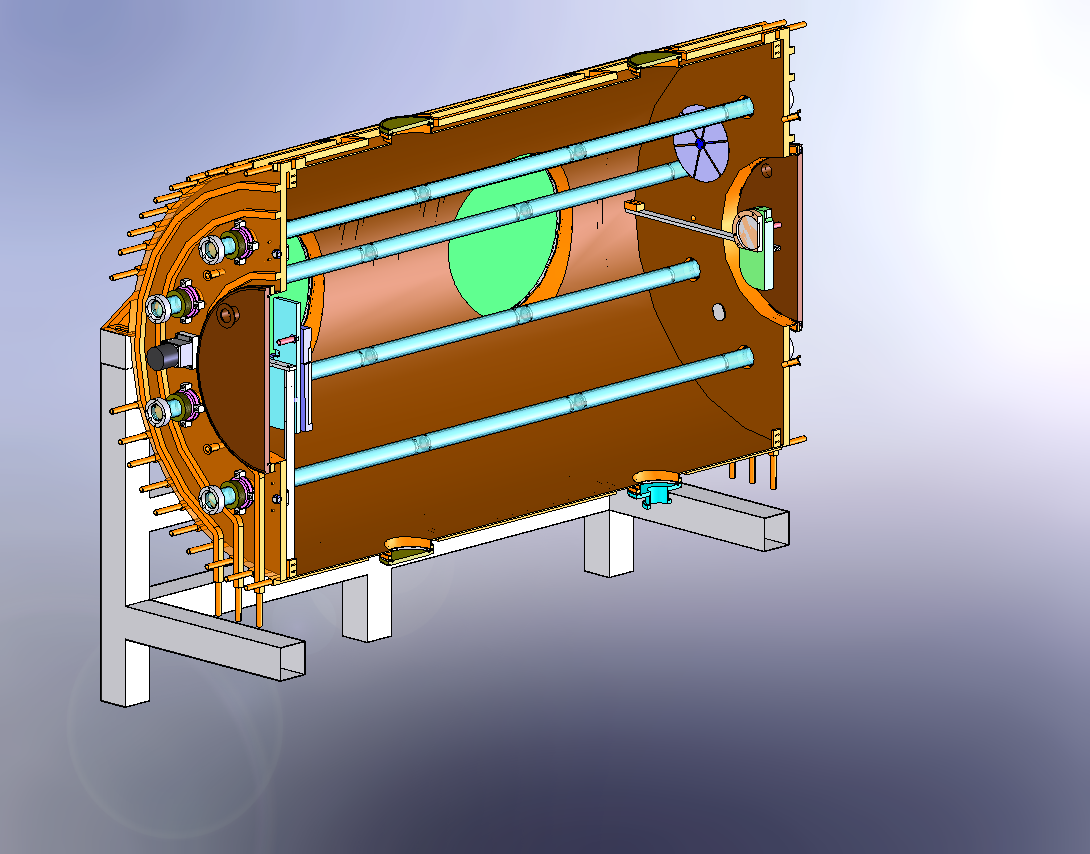 Figure 1: Solidworks cutaway to show the half the lighting system, the large ISO-K500 access flanges, one of the fans and the mounting of the FTIR mirros. 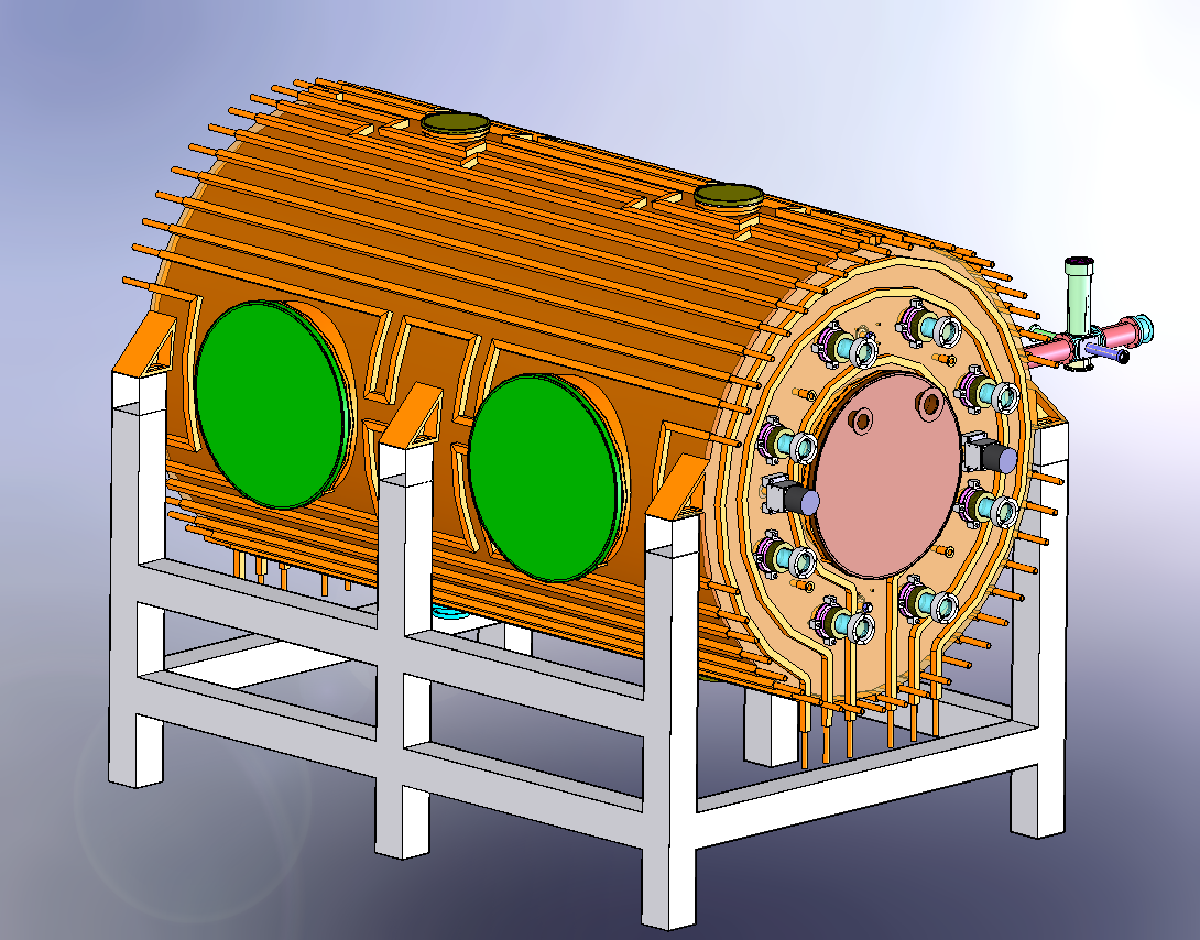 Figure 2: External view of HIRAC mounted on its frame. The design of the cooling/heating system can be seen. On the far side is the FAGE instrument for OH, HO2 and CH3O2 detection. 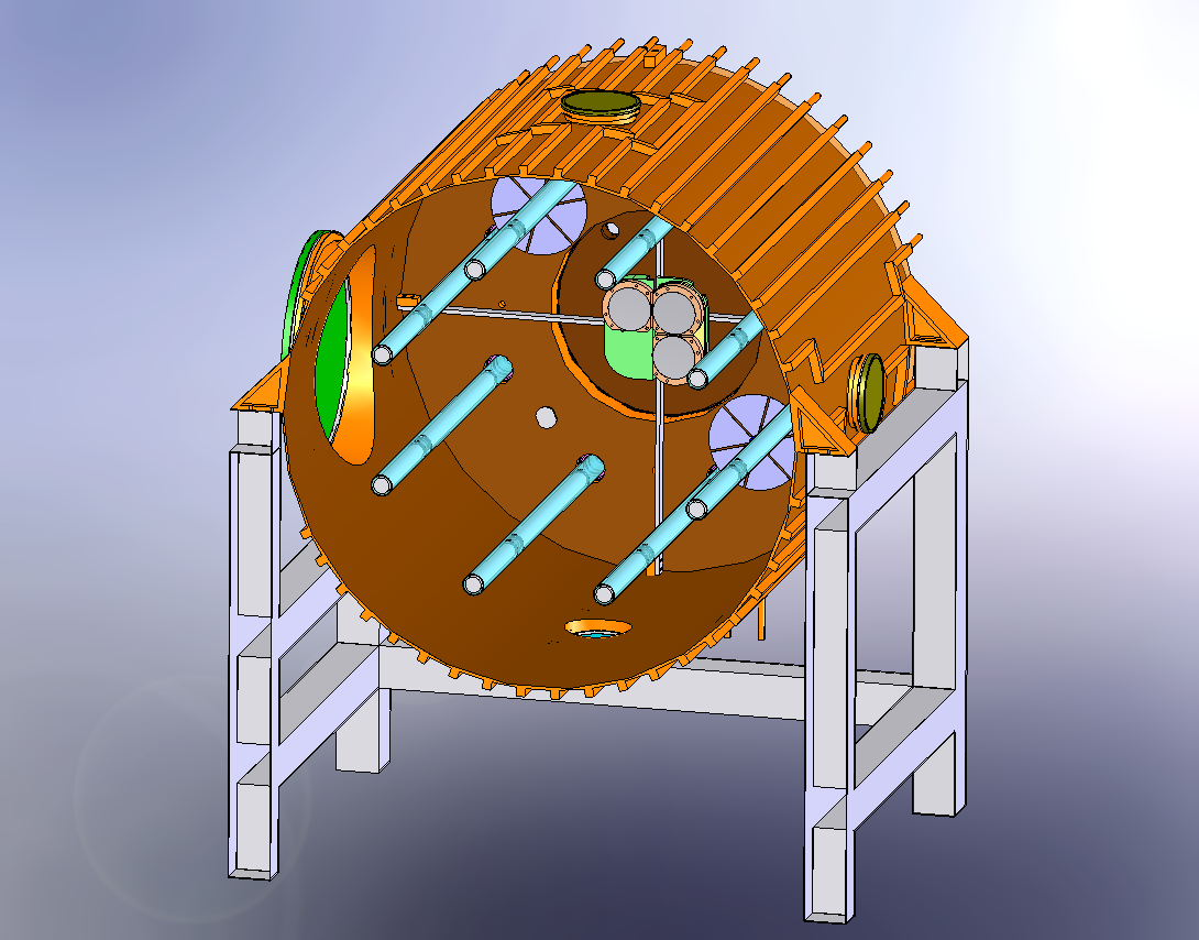 Figure 3 Solidworks, end-on view showing the distribution of internal lamps, 2 fans and the Chernin objective mirrors 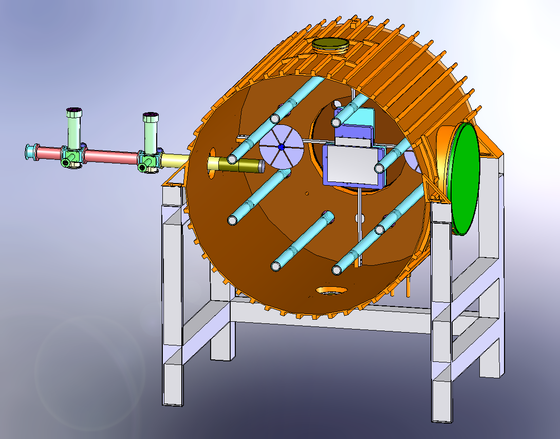 Figure 4: Solidworks, end-on view showing the location of the FAGE inlet (can be moved across the diameter of HIRAC), lights, fans and field mirrors of the Chernin cell. |
| Irradiation spectra | 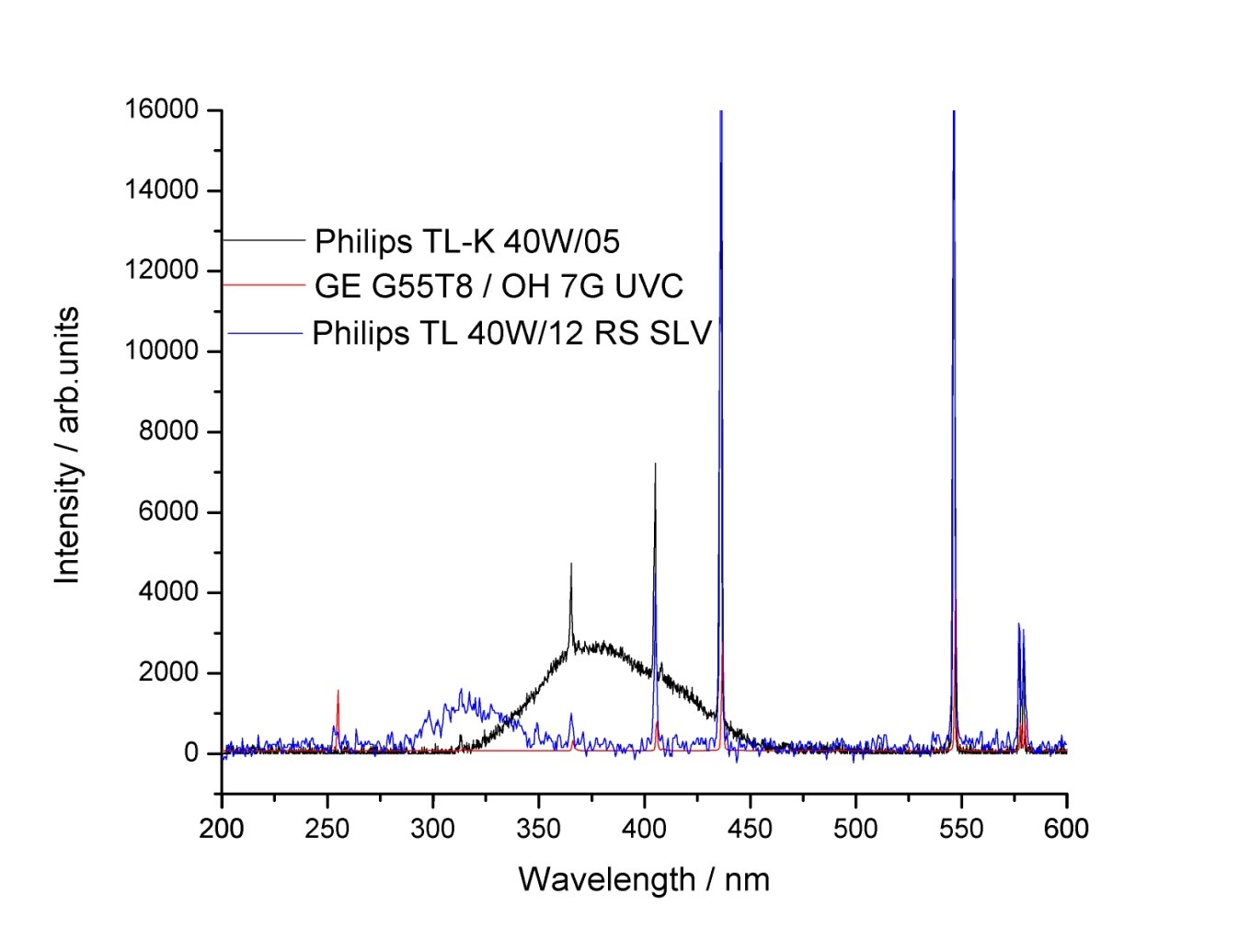 Lamp spectra for HIRAC. |
| Instrumentation | 1. FTIR – Bruker IFS/66 spectrometer, coupled to modified Chernin multipass cell (Glowacki et al. Applied Optics 46, 7872-83, 2007), pathlength 128.5 m 2. OH, HO2 detection via FAGE. (Winiberg et al. Atmos Meas. Tech 8, 523-40, 2015) 3. CH3O2 via modified FAGE (Onel et al. Atmos. Meas. Tech.10, 3985-4000, 2017) 4. HO2 via CRDS (Onel et al. Atmos. Meas. Tech. 10, 4877-94, 2017) 5. OH reactivity (Stone et al. Atmos. Meas. Tech. 9, 2827-44, 2016) 6. O3 – Thermo Electron UV model 49C 7. NO, NO2, Thermo Electron Model 42C, ~50 pptv 8. GC – HP6890 GCs with FID. 9. PTR-MS – Kore, to be added in 2018 |
| Auxiliary mechanism | In general most of the photolysis rates and wall loss rates will be checked prior to any experiments. The values of the parameters given below are typical examples, but will depend on the condition of the walls and the chamber temperature. Photolysis Rate Coefficients JNO2 ~ 2 x 10⁻³ s-1 (Philips,TL-D36W/BLB) JCl2 ~ 1.5 x 10⁻⁴ s-1 (Philips,TL-D36W/BLB) JHCHO ~ 3.6 x 10⁻⁵ s-1 (Philips, TL40W/12RS) Jt-ButOOH ~ 3 x 10⁻⁵ s-1 (254 nm lamps GE Optica) Wall Production of HOx Depends strongly on the condition of the walls and typically insignificant following cleaning (either manual cleaning or heating the walls with pumping and illumination). Production rates can be measured in the absence of the photolysis precursor and even in the worse cases are <10% of gas phase production. Wall Loss Rate Coefficients O3 = (1.5 – 4) x 10-5 s-1 (at room temperature, increases with T) NO2 = ~4 x 10⁻⁵ s-1 HO2 = (0.03 – 0.07) s-1 VOC – non polar VOC such as alkanes are stable over periods of >30 mins (less than 1% loss giving kwall < 5 x 10⁻⁶ s-1). Polar species (e.g. organic acids) do have measurable loss rates over these timescales with kwall ~ (2-7) x 10-5 s-1. Determined by direct measurements of pure compounds or, if these are not available, estimated by analogy with structurally similar compounds 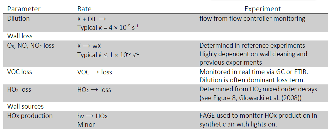 |
| Instrumentation papers | 1. Design and initial results – Glowacki et al. ACP 7, 5371-5390, 2007. 2. FTIR Multipass Optics – Glowacki et al. Applied Optics 46, 7872-83, 2007 3. OH, HO2 detection and calibration via FAGE. (Winiberg et al. Atmos Meas. Tech 8, 523-40, 2015) 4. OH reactivity instrument (Stone et al. Atmos. Meas. Tech. 9, 2827-44, 2016) 5. CH3O2 via modified FAGE (Onel et al. Atmos. Meas. Tech.10, 3985-4000, 2017) 6. HO2 via CRDS (Onel et al. Atmos. Meas. Tech. 10, 4877-94, 2017) |